Read the latest articles, news, and company updates from Fortress. Explore our insights on industry trends, product launches, and upcoming events to keep you connected and informed.
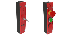
Our sales team are on hand to help provide the perfect interlock solution for your industry; or, with our product configurator, you fill in a quick form outlining your specific needs, to generate a custom configuration part number.
Stay ahead with the latest in safety solutions. Sign up for our newsletter to receive expert insights, industry updates, and exclusive content straight to your inbox.