How to use Trapped Key Interlocking to Enhance Lockout / Tagout
Using Trapped Key Interlocking to enhance a LOTO procedure can give peace of mind to both personnel and their supervisors that a machine has had all energy sources isolated, and all residual energy correctly discharged before access to the hazardous area is possible, they can further be reassured that the process cannot be reversed while someone is working inside the area. ANSI/ASSE Z244.1 2016 (Annex T) and BS 14100 (Clause 6.3.2) both suggest enhancing a LOTO programme with trapped key as it forces the process, providing a mechanical link between the guard access locks and the isolator reducing the risk of human error that could lead to unexpected start-up.
What is Lockout / Tagout (LOTO)?
Lockout / Tagout (LOTO) is a method of controlling hazardous energy in machinery safety used mostly for significant interventions and maintenance tasks, especially those which require dismantling the machine or removal of risk reduction measures in order to carry out the task.
Although LOTO is a popular means of controlling hazardous energy and is required for many tasks by OSHA regulations in the USA (see OSHA 29 CFR 1910.147) it is an administrative control, which is the last option in the hierarchy of controls (see here for more information on the hierarchy of controls).
LOTO relies on personnel to accurately follow what can sometimes be a complicated, multi-step process of isolating and discharging energy sources before carrying out the required task. Due to this complicated process, personnel may miss steps or fail to follow the procedure at all, accidentally or otherwise. In many Lockout / Tagout (LOTO) procedures it can be difficult to guarantee the procedure will be carried out correctly every time regardless of how much training is given or how great the threat of disciplinary action is.
ANSI/ASSE Z244.1 explains the two main ways of isolation of energy sources using Trapped Key Interlocks
1. Directly driving the contacts via a trapped key fitted to the shaft. This method would work on units that are small enough to allow the trapped key to drive directly. E.g. a key switch for electrical or fluid power where the key is released only when the power is in the off position.
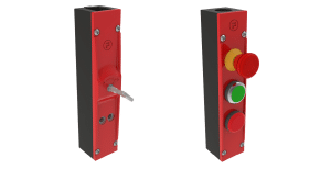
2. Having a cam mechanism and bolt lock module for units that are too large for the trapped key to directly drive. E.g. a Switch Control Unit that allows a key to be released only when the energy source is switched off, or the use of a bolt module to retrofit on an existing disconnect or fluid valve.
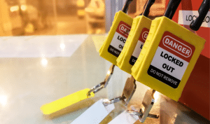
Once the key has been released from any one of these isolation devices, a Lockout padlock can be applied either directly to the isolation devices or to a cover over the keyhole which can be padlocked closed. In very simple applications the released key can be used directly to open an interlocked door and gain access to the hazardous area, knowing that while the door is open, the key is locked in the interlock and therefore cannot be used to turn the energy source back on.

More complex system will have a key exchange unit to take keys released from all energy source isolator. Only when all the energy sources have been isolated would one or more access keys be released as required to perform the task. Again, while any doors are open, the access keys will be trapped and no isolation key can be released again to turn power on unit every door is closed and locked and the key returned to the exchange unit.

It is of course possible to add in more complex logic to the system, where more steps are required. For example:
Fortress excels in solving complex energy control applications using trapped key systems. Please contact your local representative for advice and help with designing a customised solution for your Hazardous Energy Control Program. References: BS 14100:2020, ANSI/ASSE Z244.1 2016
Product Mentioned in this Article

mGard

mGard

mGard

mGard

mGard