🗄️“How can Event Data be recorded for Easy Industrial Facility Audit?”🗄️
With FRANK technology integrated into your Fortress solution, monitoring of interactions including their date, time, and frequency, can be easily recorded as event data.
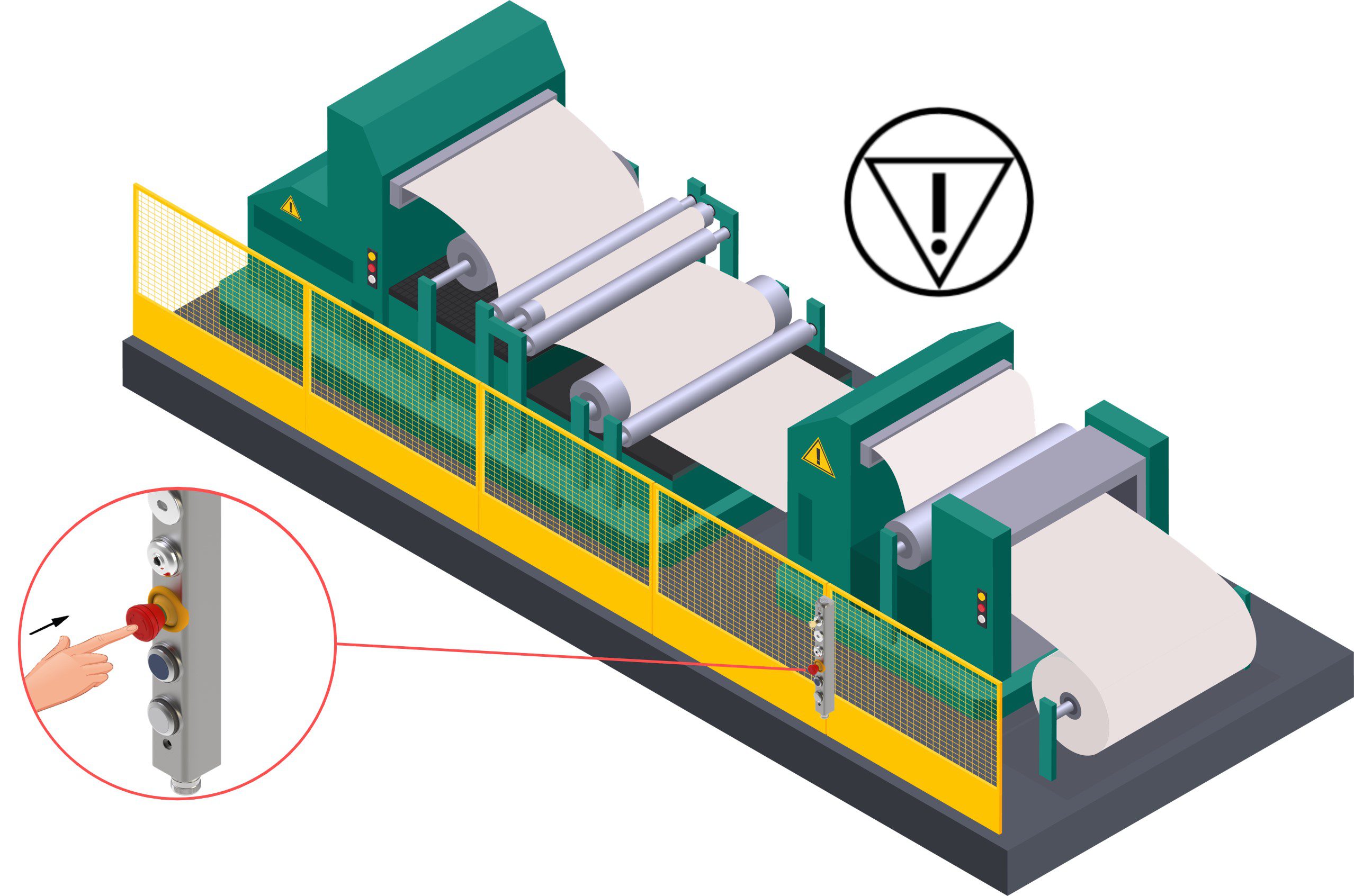
⭕ Click the elements on the image below to find out more! ⭕
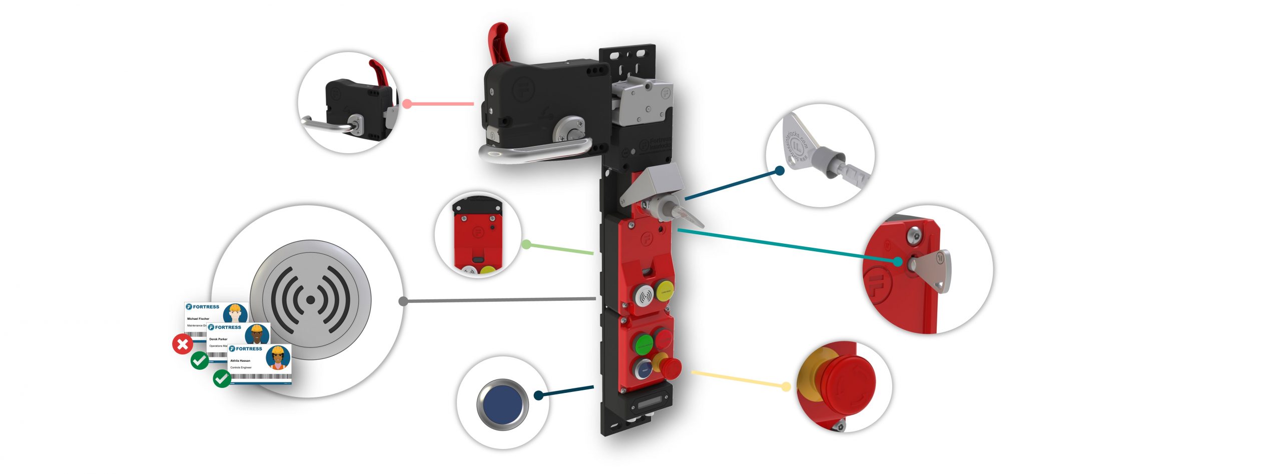
Assign Permissions to Machine functions and access to specific Individuals
Guard Locking Status
Use of a Manual Reset Function
Extraction of Safety Key or Guard opening
Auxiliary Release – Event Data
“How frequently are operators using an auxiliary release on the locking mechanism at an entry point?”
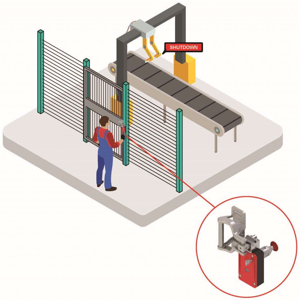

The use of an auxiliary (or emergency) release should be very rare. Operating this function whilst a machine is running can perform a machine stop command, but does not protect the operator from any residual hazardous energy as it comes to a controlled stop. Monitoring of this function is pre-installed in all ‘FRANK enabled’ Guard Locking Interlocks.
“How can interaction data be used to detect Auxiliary Release Operation?”
All FRANK enabled products are supplied with a ‘Byte Map’ or ‘Memory Map’ dictating the position of inputs and outputs. The head and solenoid monitors will be pre-assigned to the non-safe inputs as shown below (for both PROFINET and EtherNet/IP connections).
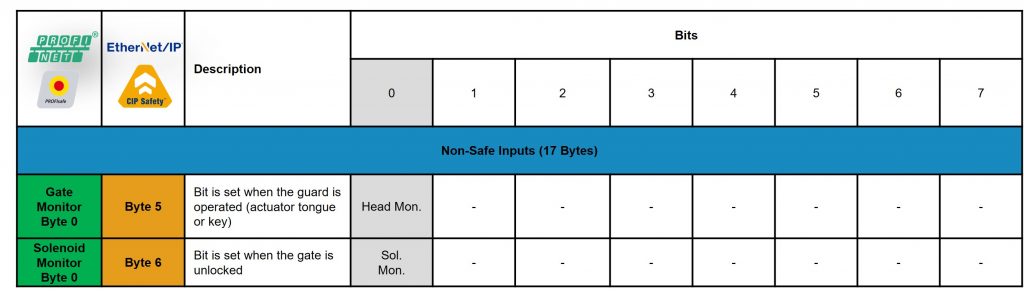
Event data will capture the use of an auxiliary release mechanism under two functions and associated with the relevant Location, Date and Time;
- Closed, Auxiliary Release – Activation of the auxiliary release
- Opened, Auxiliary Release – Opening of a guard whilst an auxiliary release is activated.

Escape Release – Event Data
“How frequently are operators becoming trapped inside the safeguarded space?”
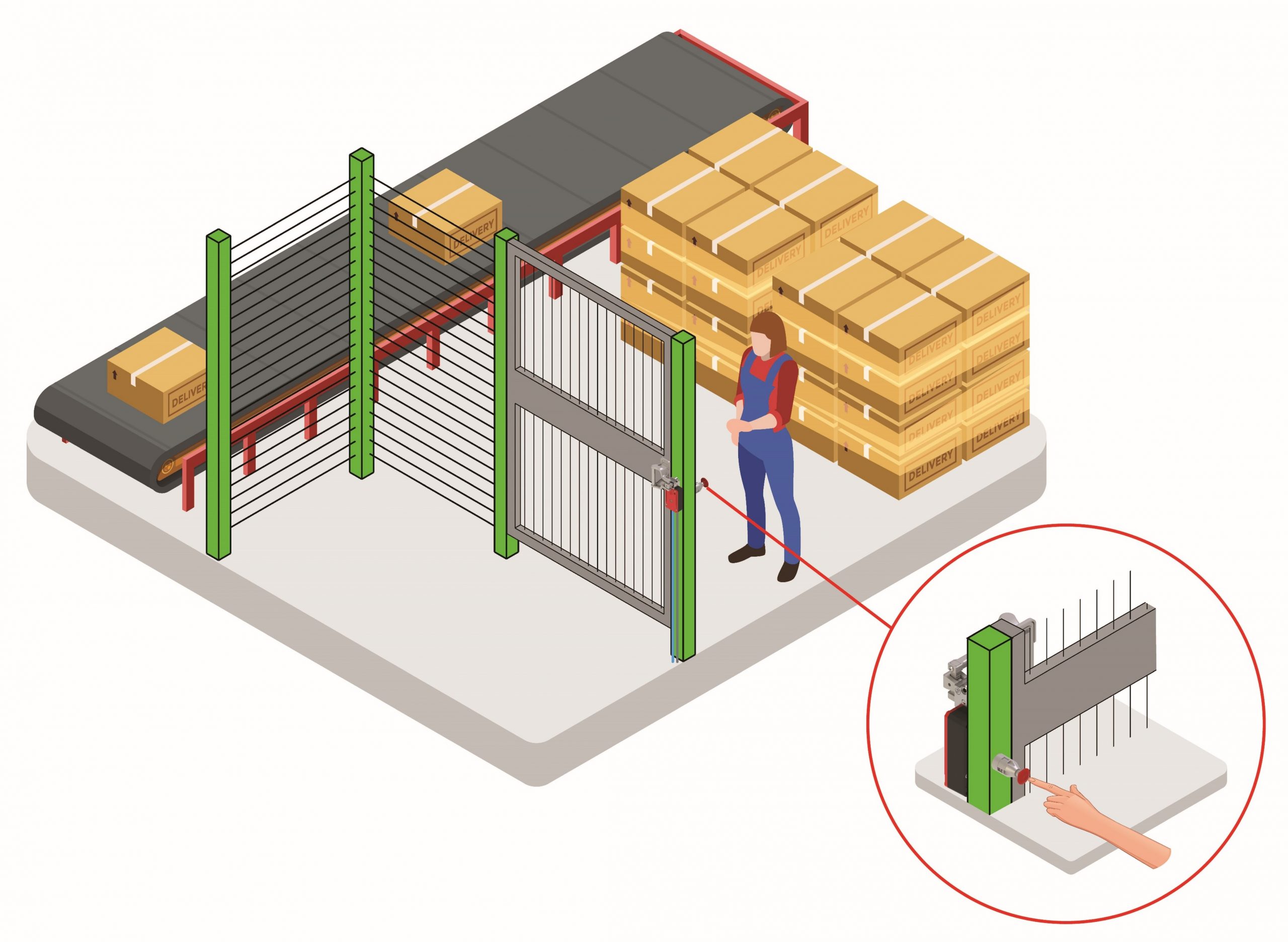
An escape release is typically used in cases of emergency to override the locking mechanism on a guard locking device and open the door to egress a hazard. Similar to an auxiliary override or emergency override, this can be used to perform a machine stop command, but instead of emergency entry, is for emergency exit suggesting ‘something has gone wrong‘. Monitoring of this function is pre-installed in all ‘FRANK enabled’ Guard Locking Interlocks.

“How can interaction data be used to detect use of an Egress Function?”
All FRANK enabled products are supplied with a ‘Byte Map’ or ‘Memory Map’ dictating the position of inputs and outputs. The solenoid monitor will be pre-assigned to the non-safe inputs as shown below (for both PROFINET and EtherNet/IP connections).
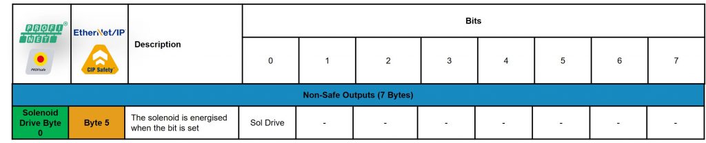
Event data will capture the use of an escape release slightly differently depending on the type of mechanism implemented – single action or dual action escape release – and associate it with the relevant Location, Date and Time;
- Opened, Escape Release – Detects the opening of a guard following an escape release. A single action escape release will appear with only this function, unless there is a ‘reset function’ on the ER.
- Closed, Escape Release – Detects the operation of an escape release mechanism whilst the guard is closed. This will typically appear when a dual-action escape release is activated, or when a guard has been closed and an escape release mechanism has not been reset.

Emergency Stop – Event Data
“How frequently has the Emergency Stop function been used?”

According to BS EN ISO 13850, the ’emergency stop device [is used to] initiate an emergency stop function… [and is part of the] safety related parts of the control system’. The use of an emergency stop is intended for urgently ending or averting a hazardous situation, therefore its’ operation is often recorded for facility auditing.
“Looking for an easy way to track Emergency Stop Activation?”
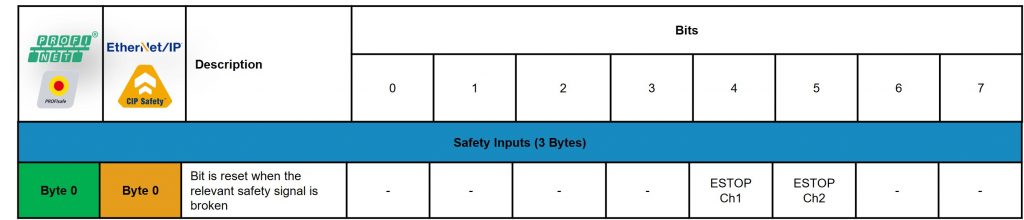
Emergency stop monitoring bytes are located in the Safety Inputs under Byte 0, bits 4&5.
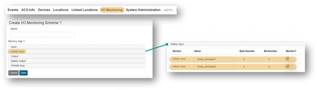
The emergency stop utilises a dual-channel safety input position on the Fortress device. Monitoring of Estop operation can be associated to both individual inputs or just one in an ‘I/O Monitoring’ scheme. This can be navigated via the FRANK local access. In Safety Input, the Estop inputs can be monitored by renaming Safety_Input 0_4 and 0_5 and applying this monitoring to the relevant locations and devices.
Event data will capture the the activation and reset of an emergency stop and associate it with a specific Location, Date and Time. Where ‘Safety_Input 0_4 and 0_5′ have been named Estop_Activation1 and Estop_Activation2, event data can be collected for;
- Estop_Activation.. : False – to signify operation of an emergency stop
- Estop_Activation.. : True – to signify the reset of an emergency stop
