Pneumatic Monitored Safety Valves
Pneumatic Monitored Safety Valves from Fortress Fluidsentry have become globally recognised as key components in safety related parts of fluid power control systems. Fortress’s monitored valve technology is designed as an interface between the pneumatic operation & electrical safety circuits of machinery.
If an Electrical powered system is designed for Cat. 4, SIL 3, PLe, why wouldn’t the Pneumatic powered system be designed to the same level?
Understanding Pneumatic Monitored Safety Valves
The Pneumatic Monitored Safety Valve (PSV) can be retrofitted to control hazardous residual pressure in pneumatic systems by isolating the upstream source.
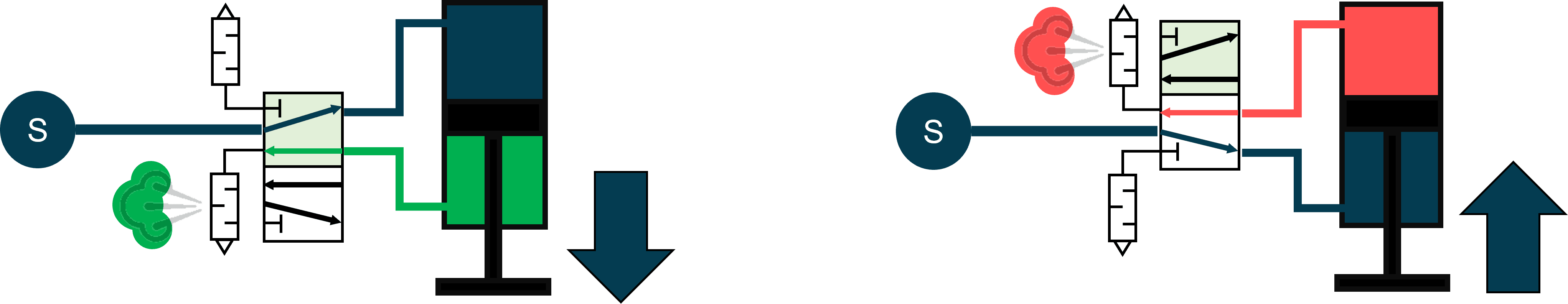
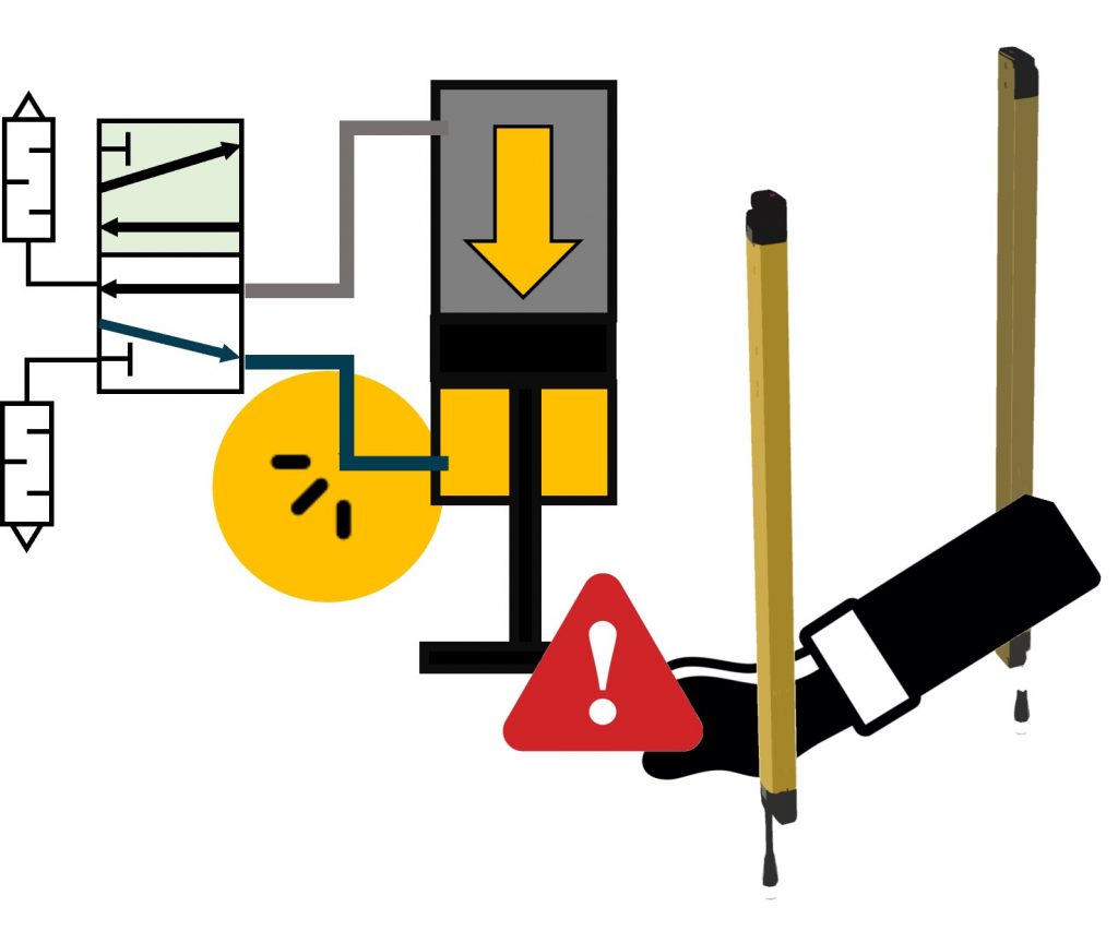
In the video below, ‘S’ shows the source of pneumatic energy. This directional valve is energised and de-energised to move a linear actuator (such as that used in a press).
The two states of a standard 3-2 directional control valve are shown below; through energisation of the solenoid controlling valve position, the direction of incoming pneumatic energy can swap between the red and green sections pictured. In the left hand image, pneumatic energy is entered into the top chamber from the source, causing the ‘green’ chamber to release stored energy through the exhaust (thus moving the linear actuator down shown in black).
De-energisation of the solenoid will change the direction of the incoming pressure. On the right hand image, this is shown by entering the bottom chamber from the source, and exhausting the contents of the red chamber to atmosphere. This will cause the linear actuator to move up.
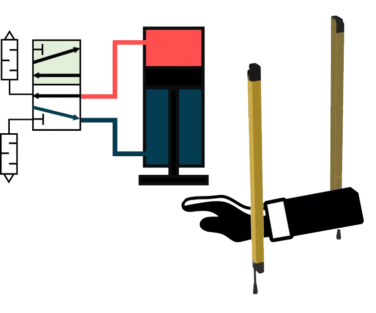
What happens if access to this linear actuator is required?
Many systems are designed only to remove power to controls, motors and valves. Here’s an example of a point of operation where breakage of this light curtain beam isolates electrical power to the directional control valve to stop ‘intentional movement’.
But, there are lots of things that could go wrong in pneumatics…
❗ Broken or Non-moving Components ❗
🐌 Sluggish Response to energisation 🐌
❌ Pilot Seal Failure causing unexpected motion ❌
⏲️ Slow or Sticking Valve affecting Response Time ⏲️
💧 Leakage or Improper Sealing of Components 💧
🦠 Internal Wear and Contaminants 🦠
💬⚠️
“What Happens if an inlet bursts on a gravity load? Would removing power stop it from falling?“
“What happens is a valve fails to close due to contamination? Could a cylinder keep moving?“
“What happens if a cylinder fails? Would turning off the power to the valve stop it from descending?“
Crushing and shearing hazards are commonly found at the point of operation of machinery driven by fluid power loads such as pneumatics.
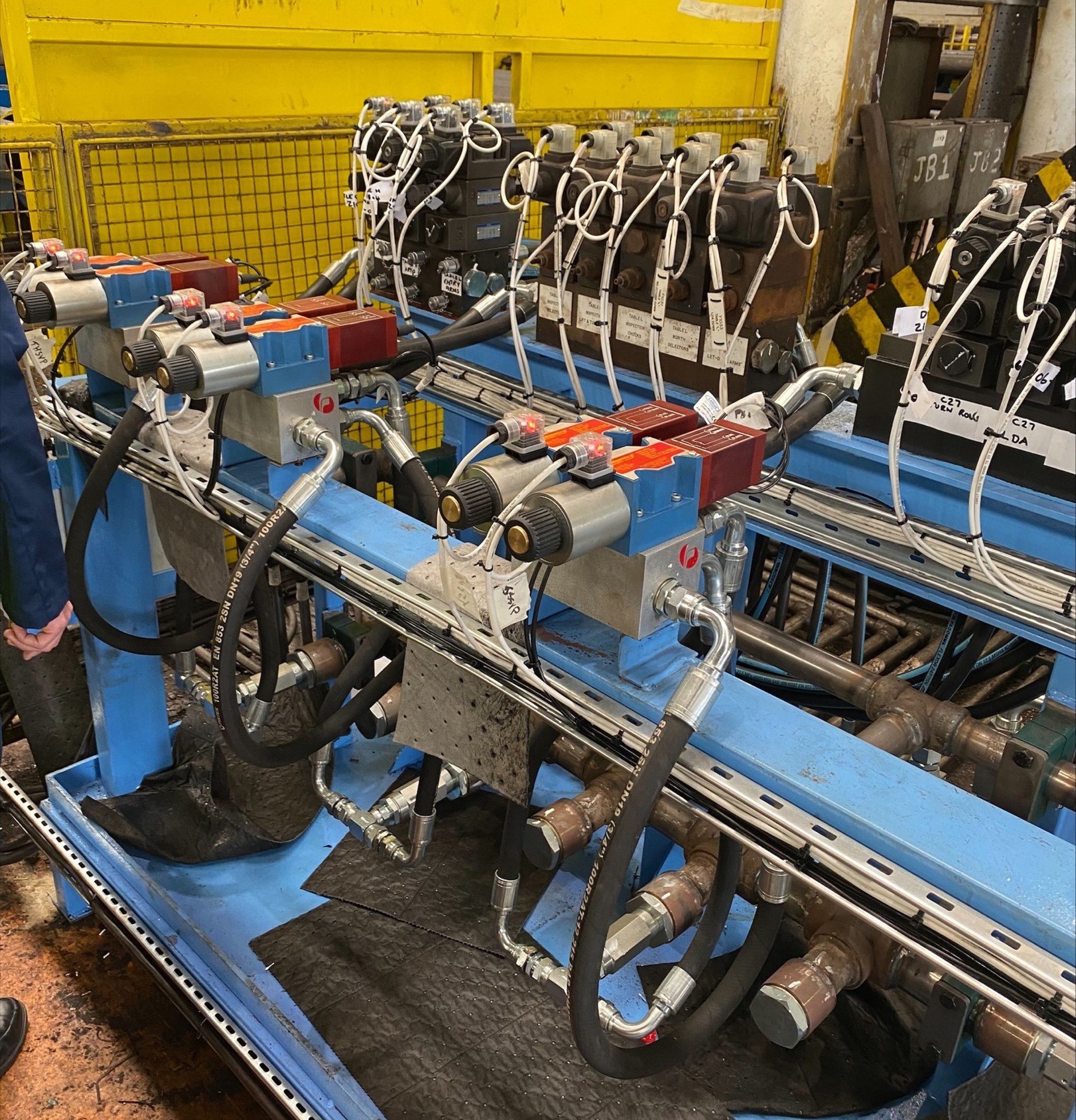
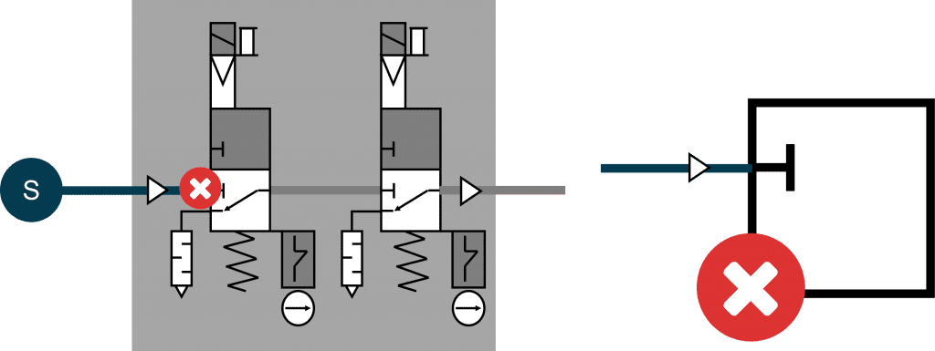
🦺 Pneumatic Monitored Safety Valves placed in Series with the Machine Supply
The pneumatic safety valve is place in series with the machine supply. Supplying 24V to the Pneumatic Monitored Safety Valve (PSV) enables the pneumatic energy or fluid power to flow through.
As soon as the Fortress PSV is de-energised, the downstream system is isolated and residual energy is exhausted.
Here’s how the pneumatic monitored safety valves prevent single point of failure.
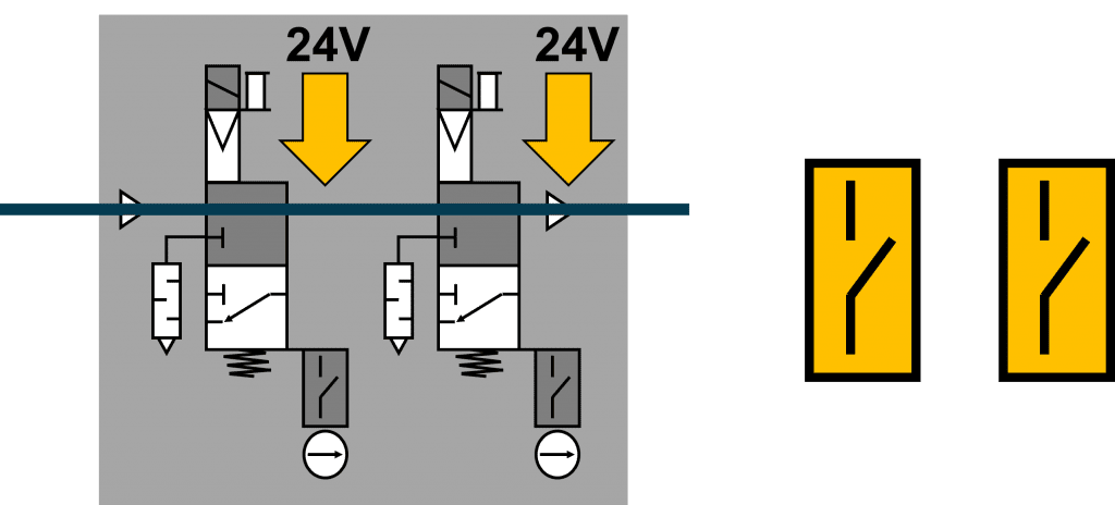
✅ When the valve element is in the energised position, safety device contacts are positively driven open
(When the valve is energised (i.e. 24V is supplied to the solenoid), closed contacts are opened)
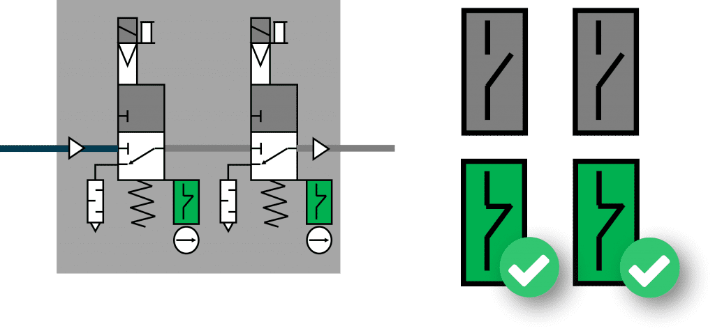
✅ When electrical signal is removed, fluid supply blocked and vented from hazardous motion
(When the 24V is removed, the valve blocks supply of fluid power through the valve and exhausts downstream energy to atmospheric pressure)
✅ Mechanical Bias to exhaust downstream fluid power
(There is a bias of motion, such that removal of the 24V will guarantee incoming fluid power is isolated and downstream pneumatic energy is removed)
✅ Safety rated device monitors position of the valve element in de-energised state
✅ Dual NC contacts are directly operated by the element in the transition to output state
(A highly reliable limit switch makes direct contact with the spool in the valve providing dependable feedback)
✅ The SRP/CS shall ensure both independent valve elements have transitioned by monitoring independent contacts
✅ Fault condition possible from non-synchronous motion of independent elements
(Independent switch contacts on each monitoring system detect motion of both vales, ensuring their synchronicity to identify faults)
How do they work with your control system?
Monitored safety valves act as an output within the control system.
Input ➡️ – Logic 💻 – Output ➡️
Outputs directly enable or control the power to the machine actuators that produce hazardous motion e.g. contactors or fluid power valves.
In a Category 4 system, all components within the system must meet that same level of safety. If there is Pneumatic energy inside a safeguarded space, isolation of the energy (and removal of residual energy) must occur before the Logic in the system (the safety PLC) can unlock the Input (an interlock or access control device) and allow interaction with the pneumatic hazard.
Our Solutions
Selecting your Pneumatic Monitored Safety Valves
The Valve type selected will depend on the flow factor or port connection size. Select from the types below for more information on each product.
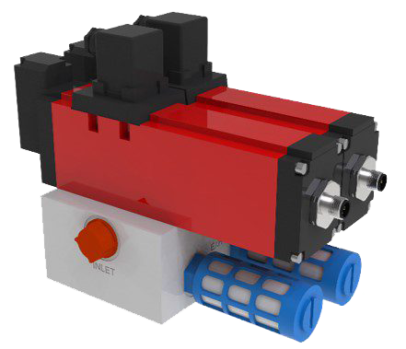
PSV-0DAD-2-G050-MP0
PSV (Pneumatic Safety Valve) – 0DAD (Block and Bleed, 3.7 Cv flow rate, M12 connection) – 2 (Dual Valve) – G050 (1/2″ BSP Port Size) – MP0 (standard manifold mounting from rear)
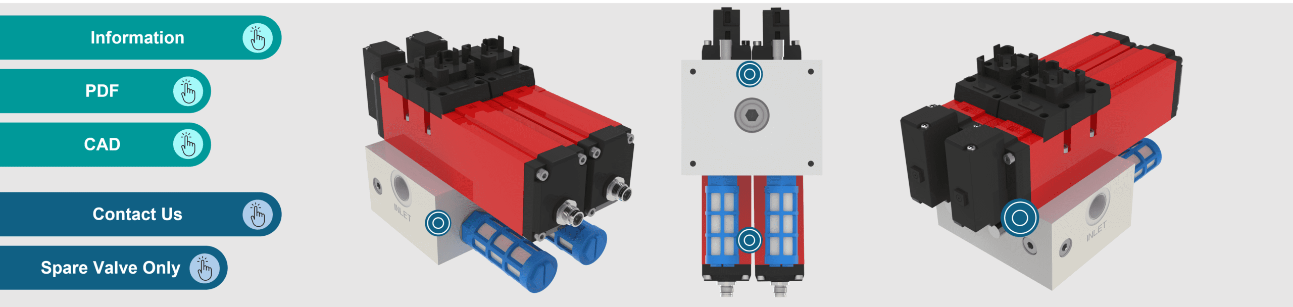

🔵 1/2″ single 5 port 2 position solenoid spool valve
🔵 Mounted on safety manifold configured for 3/2 operation
🔵 Positive opening spool monitoring switch.
PSV-0DAD-S
Fortress Fluidsentry valves are designed for easy maintenance with the understanding that urgent situations require urgent attention. Where a valve is not operating as expected, a spare can be swapped in within minutes to minimise the impact of downtime.
🟢 Port Connection – 1/2” BSP
🟢 Suitable for use in systems up Cat. 4, PLe.
🟢 Operating Temp.: up to +50 C
🟢 Cv Flow Factor (P to A) 3.7
🟢 Working Pressure Range: 250 - 1000kPa
🟢 Max. Operating Freq.: 5Hz
⏳ Activation Time: 19ms
⏳ Deactivation Time: 65ms
💨 Medium: Compressed Air filtered to 5 micron and/or filtered
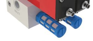
2x 1/2" Silencers
2x Switch monitored safety valves
Cross-linked series ported manifold
PSV-0EAD-2-G075-MP0
PSV (Pneumatic Safety Valve) – 0EAD (Block and Bleed, 5.5 Cv flow rate, M12 connection) – 2 (Dual Valve) – G075 (3/4″ BSP Port Size) – MP0 (standard manifold mounting from rear)
🔵 3/4″ single 5 port 2 position solenoid spool valve
🔵 Mounted on safety manifold configured for 3/2 operation
🔵 Positive opening spool monitoring switch.
PSV-0EAD-S
Fortress Fluidsentry valves are designed for easy maintenance with the understanding that urgent situations require urgent attention. Where a valve is not operating as expected, a spare can be swapped in within minutes to minimise the impact of downtime.
🟢 Port Connection – 3/4” BSP
🟢 Suitable for use in systems up Cat. 4, PLe.
🟢 Operating Temp.: up to +50 C
🟢 Cv Flow Factor (P to A) 5.5
🟢 Working Pressure Range: 250 - 1000kPa
🟢 Max. Operating Freq.: 5Hz
⏳ Activation Time: 25ms
⏳ Deactivation Time: 110ms
💨 Medium: Compressed Air filtered to 5 micron and/or filtered
2x 3/4" Silencers

Cross-linked series ported manifold
Two independently solenoid controlled valves.
PSV-0FAD-2-G100-MP0
PSV (Pneumatic Safety Valve) – 0FAD (Block and Bleed, 8.2 Cv flow rate, M12 connection) – 2 (Dual Valve) – G100 (1″ BSP Port Size) – MP0 (standard manifold mounting from rear)

🔵 1″ single 5 port 2 position solenoid spool valve
🔵 Mounted on safety manifold configured for 3/2 operation
🔵 Positive opening spool monitoring switch.
PSV-0FAD-S
Fortress Fluidsentry valves are designed for easy maintenance with the understanding that urgent situations require urgent attention. Where a valve is not operating as expected, a spare can be swapped in within minutes to minimise the impact of downtime.
🟢 Port Connection – 1” BSP
🟢 Suitable for use in systems up Cat. 4, PLe.
🟢 Operating Temp.: up to +50 C
🟢 Cv Flow Factor (P to A): 8.2
🟢 Working Pressure Range: 250 - 1000kPa
🟢 Max. Operating Freq.: 2Hz
⏳ Activation Time: 35ms
⏳ Deactivation Time: 140ms
💨 Medium: Compressed Air filtered to 5 micron and/or filtered
2x 1" Silencers

Cross-linked series ported manifold

Two independently solenoid controlled valves.
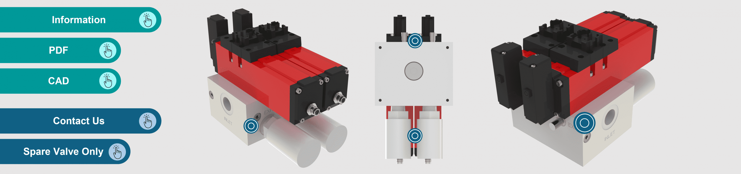
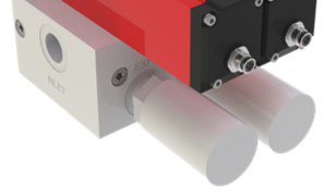
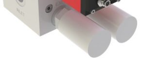
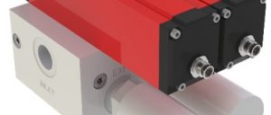
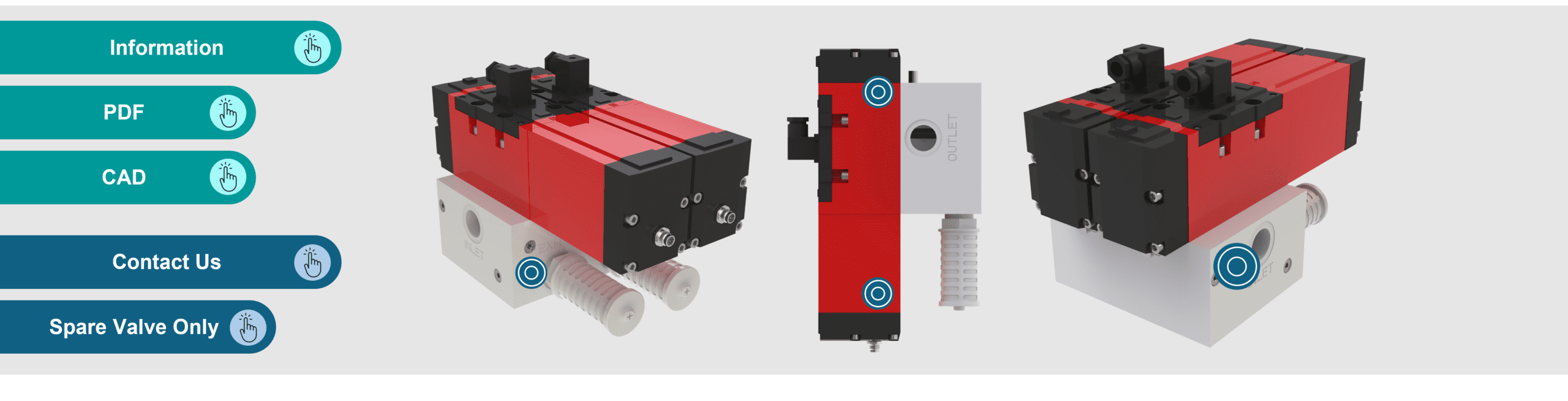
What are the Port Connections?
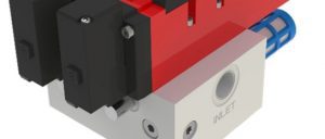
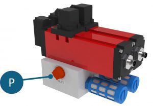
Inlet ‘P’ Port
The supply port or ‘P Port’ supplies the valve from the upstream energy source. When the pneumatic safety valve (PSV) is activated, the P port enables the flow of compressed air through the valve to the downstream process. When the PSV is deactivated, the P port is blocked.
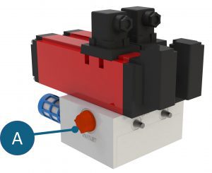
Outlet ‘A’ Port
In the energised state, the A port receives the input of compressed air from the P port enabling the flow of energy to the downstream process. In the isolated state, downstream pressure from the ‘A’ port is redirected to the exhaust ports to remove hazardous energy.
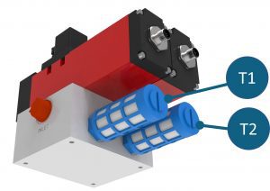
Exhaust Ports ‘T1 and T2’
The exhaust ports T1 and T2, provide a means to release pressurised air when a pneumatic hazard is isolated.
(Ports are measured in BSP – British Standard Pipe (as defined in ISO 228))
What is Activation and Deactivation Time?
Activation time is the time to activate the switches from the solenoid energised state to the solenoid isolated state (i.e. time to transition from energy transfer from P to A enabled to P port blocked, A to tank).
Deactivation time – time to deactivate the switches from the isolated state and return the valve to the solenoid energised state (i.e unblock the P port and enable P to A flow).
See all downloads and technical information on the fluid power overview page or on the main downloads page.
Downloads and Technical Info
See all downloads and technical information on the fluid power overview page or on the main downloads page.